WDY
Miller Consulting Engineers
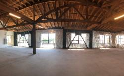
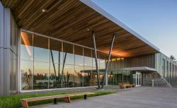
The 55,000-sf two-wing military headquarters building accommodates anti-terrorism measures which required design loading per the Unified Facilities Criteria Code. These out-of-plane loads far exceed traditional wind or seismic loads up to the level required for the main force resisting elements. Each wing utilizes independent lateral systems of steel special concentrically braced frames. Construction and detailing considerations allowed occupancy just 14 months after breaking ground.
Owner/Developer: The Oregon Military Department
Architect: SERA Architects
General Contractor: Fortis Construction
Equilibrium Engineers
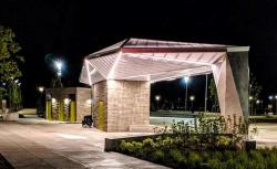
The entry pavilion utilizes chamfered lines connecting site elements and the art piece depicts an abstracted butterfly emerging from a chrysalis. The complexity of the polycarbonate panel cladding pavilion roof was achieved through a system of articulated HSS ribs and a center truss-supported spine. Each angle of the chamfered roof was unique to the others. Connections between roof and wall elements were not readily apparent to the eye, creating the impression of a floating roof.
Owner/Developer: Portland Parks and Recreation
Architect: Scott Edwards Architecture / PLACE Landscape Architects
General Contractor: R & R General Contractors, L&M
Steel Fabricators, Custom Designed Skylights
Miller Consulting Engineers
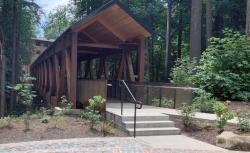
The new clear-span pedestrian bridge expands beyond the original in order to avoid new foundations within the environmental zone. Eliminating interior supports and utilizing micro piles as abutment supports limited the heavy equipment required within the ravine. Wood trusses provided a roof along the top chords and walking surface along the bottom chords. Locally-sourced components were fabricated off site and shipped in sections, reducing installation time and cost.
Owner/Developer: Lewis & Clark College
Architect: Minarik Architecture, Inc.
General Contractor: Precision Construction Company
KPFF Consulting Engineers
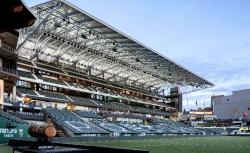
The Providence Park Stadium Eastside Expansion aimed to create as many additional seats as possible to accommodate the rapidly increasing Thorns FC and Timbers FC fanbase. All construction work had to co-exist with the original construction as well as numerous expansions and renovations. Over 200 micro-piles were drilled from the street level down to the field level. Due to the two-story elevation difference between the street and field, transfer beams were used at street level to transfer the superstructure columns into practical foundation locations. A structural diaphragm also exists at grade level linking the discrete pile caps and transfer beams. A special concrete moment frame seismic force resisting system was used in both directions. Concrete raker beams and seating trays were cast off-site and hung from specially designed connections at the site-cast frames in order to provide field sightlines. In order to maximize the limited footprint, a larger number of cantilevers, the maximum being 32 feet, were used in the PT concrete beam and slab system. A 120-foot-long cantilever roof canopy was designed to provide covering for all new seating. This woven field of members desired by the architect was surface-modeled in a 3D program which provided geometry for structural analysis and member sizing. The architect, engineer, contractor, and shop detailer attended weekly 3D model sharing and overlay sessions to ensure exact design geometry was followed through into fabrication. In the end, 4,000 seats were added to the stadium, raising the capacity to approximately 25,000 fans.
Owner/Developer: Portland Timbers / Peregrine Sports
Architect: Allied Works
General Contractor: Turner Construction